Showing posts with label Faraday’s law. Show all posts

Electromagnetism - Faraday’s law


The circuit shown is in a uniform magnetic field that is into the page and is decreasing in magnitude at rate of 150 tesla/second. The ammeter reads


A. 0.15 A
B. 0.35 A
C. 0.50 A
D. 0.65 A
E. 0.80 A
(GR9677 #02)

Solution:

IR − ɛ = 0
= (V − ɛ)/R

ɛ = − dΦ/dt = −AdB/dt

Given:
dB/dt = −150 t/s (minus sign because it’s decreasing)
A = (0.1 m)= 0.01 m2
R = 10 Ω
V = 5 V

ɛ = − (0.01)(−150) = 1.5 V
= (5 − 1.5)/10 = 3.5/10 = 0.35 A

Answer: B

Electromagnetism - Faraday’s law


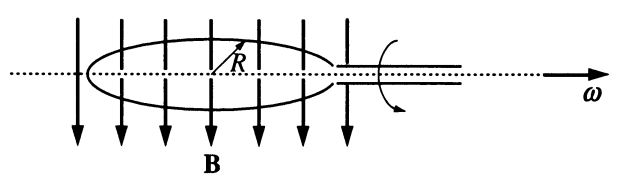
A circular wire loop of radius R rotates with an angular speed ω in a uniform magnetic field B, as shown in the figure. If the emf ɛ induced in the loop is ɛ0 sin ωt, then the angular speed of the loop is

A. ɛ0 R/B
B. 2πɛ0/R
C. ɛ0/BπR2
D. ɛ02/BR2
E. tan−1(ɛ0/Bc)
(GR9677 #46)
Solution:

Faraday's Law: ɛ = − dΦ/dt
with  Φ = NBA  

Given:
= 1
B uniform (constant)
ɛ =  ɛ0 sin ωt

→ ɛ = − B dA/dt =  ɛ0 sin ωt
− B dA =  ɛ0 sin ωdt 
 B ∫dA =  ɛ0 ∫ sin ωdt 
− BπR2 = − ɛ0/ω  cos ωt
ω = ɛcos ωt / BπR2

at t = 0,
ω ɛ/ BπR2

Answer: C


Alternative solution:
πR cos ωt
ɛ = − dΦ/dt = − B dA/dt 
ɛ = − BπR d(cos ωt)/dt 
ɛ0 sin ωt BπR2ω  sin ω
ɛ0BπR2ω  
ω ɛ/ (BπR2)

Electromagnetism - Faraday’s law


A wire is being wound around a rotating wooden cylinder of radius R. One end of the wire is connected to the axis of the cylinder, as shown in the figure. The cylinder is placed in a uniform magnetic field of magnitude B parallel to its axis and rotates at N revolutions per second. What is the potential difference between the open ends of the wire?

A. 0
B. 2πNBR
C. πNBR2
D. BR2/N
E. πNBR3
(GR9677 #47)
Solution:

Faraday's Law: ɛ = − dΦ/dt
with  Φ = NBA  

Given:
revolution per second
uniform (constant)
constant

ɛ = − BA dN/dt
= − BπR2N

|ɛ| = πNBR2

Answer: C

Electromagnetism - Maxwell's Equation

Listed below are Maxwell’s equations of electromagnetism. If magnetic monopoles exist, which of the these equations would be INCORRECT?

I. Curl H = J + ∂D/∂t
II. Curl E = −∂B/∂t
III. div D = ρ
IV. div B = 0

A. IV only
B. I and II
C. I and III
D. II and IV
E. III and IV
(GR9277 #13)
Solution:

Gauss' law of magnetism: ∇ · B = 0
→ There is no magnetic monopole
If there is one, ∇ · B ≠ 0

Faraday's law of induction: ∇ × E = −∂B/∂t
→ if there is magnetic monopole, ∇ × E = −∂B/∂t + (current of magnetic monopole)

Answer: D

Electromagnetism - Lenz's Law

Questions 54-55.


A rectangular loop of wire with dimensions shown above is coplanar with a long wire carrying current I. The distance between the wire and the left side of the loop is r. The loop is pulled to the right as indicated. 

What are the directions of the induced current in the loop and the magnetic forces on the left and the right sides of the loop as the loop is pulled? 


Induced Current         Force on Left Side      Force on Right Side
A.      CounterclockwiseTo the leftTo the right
B.CounterclockwiseTo the leftTo the left
C.CounterclockwiseTo the rightTo the left
D.ClockwiseTo the rightTo the left
E.ClockwiseTo the left To the right

(GR9277 #54)
Solution:

Lenz Law: The tendency of nature to resist any change in magnetic flux passing through a loop of wire.

When the loop is pulled away, it feels a decreasing current and resists the change of magnetic flux by inducing an increasing current in the same direction as I. 

→ The induced current in the loop is clockwise. A, B, C are FALSE.
Magnetic force between two currents


Since the current in the loop is clockwise:
  • current in the left side of the loop is parallel to the long wire, they are attracted to each other → the force on the left is to the left.
  • current in the right side of the loop is antiparallel to the long wire, they are repelled to each other → the force  on the left is to the right.
Answer: E

Electromagnetism - Faraday's Law


A uniform and constant magnetic field B is directed perpendicularly into the plane of the page everywhere within a rectangular region as shown above. A wire circuit in the shape of a semicircle is uniformly rotated counterclockwise in the plane of the page about an axis A. The axis A is perpendicular to the page at the edge of the field and directed through the center of the straight-line portion of the circuit. Which of the following graphs best approximates the emf ε induced in the circuit as a function of time t?


(GR9277 #57)
Solution:

Faraday's Law: ɛ = − dΦ/dt
with  Φ = NBA  

Given:
N = 1,
B constant
A increases and decreases uniformly since the wire circuit rotates uniformly
→  the rate of change of A, dA/dt = constant.

ɛ = − BdA/dt  = constant

Only graph (A) shows constant ε.
ε changes periodically from positive to negative since only half of area covered in magnetic field.

Answer: A

Electromagnetism - Faraday’s law


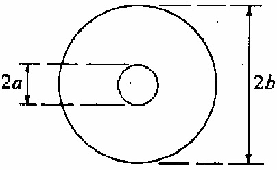
A small circular wire loop of radius a is located at the center of a much larger circular wire loop radius b as shown above. The larger loop carries an alternating current I = I0 cos ωt, where I0 and ω are constants. The magnetic field generated by the current in the large loop induces in the small loop an emf that is approximately equal to which of the following? (Either use mks units and let μ0 be the permeability of free space, or use Gaussian units and let μ0 be 4π/c².)

A.
B.
C.
D.
E.
(GR8677 #81)
Solution:

Faraday's Law: ɛ = − dΦ/dt
with  Φ = NBA  

Biot Savart Law: B ~ I

Given:
I = I0 cos ωt → B ~ I0 cos ωt
Area of smaller loop with radius a, A = πa²
N = 1

Φ = BA ≈ πa² I0 cos ωt
ɛ ~ dΦ/dt πa² ω I0 sin ωt

Only (B) fits the equation.

Answer: B


Complete Calculation:

Faraday's Law: ɛ = − dΦ/dt
with  Φ = NBA  

Magnetic field at the center of a current wire loop:  (Proof)
For the larger loop with radius b, carrying I = I0 cos ωt →

Area of smaller loop with radius aA = πa²

N = 1

Electromagnetism - Faraday’s law


A coil of 15 turns, each of radius 1 centimeter, is rotating at a constant angular velocity ω = 300 radians per second in an uniform magnetic field of 0.5 Tesla, as shown in figure. Assume at time t = 0 that the normal  to the coil plane is along the y-direction and that the self-inductance of the coil can be neglected. If the coil resistance is 9 ohms, what will be the magnitude of the induced current in milliamperes?

A. 225π sin ωt
B. 250π sin ωt
C. 0.08π cos ωt
D. 1.7π cos ωt
E. 25π cos ωt
(GR0177 #86)
Solution:

Ohm’s Law: ɛ V = IR
→  ɛ R

Faraday's Law: ɛ = − dΦdt

Magnetic Flux:  dΦB =  NBdA

At time t = 0, the normal to the coil plane is along the y-direction.

It means: n̂ ∥ ŷ BA → Φ= 0

→ Φ=  NBA sin ωt, since Φ(t = 0) = 0

ΦB = − NBπr2 sin ωt
ɛ = − dΦdt = NBπr2 ω cos ωt

=  ɛ R = (NB0ωr2/ Rπ cos ωt

 = 15 turns
B0 = 0.5 Tesla
ω = 300 rad/s
 = 1 cm =  102  m
= 9 ohms

= (15 ×  0.5 × 300 × 10−4 9π cos ωt
= (25 × 10−3π sin ωt Ampere
= 25 π sin ωt milliAmpere

Answer: E